DLPC410
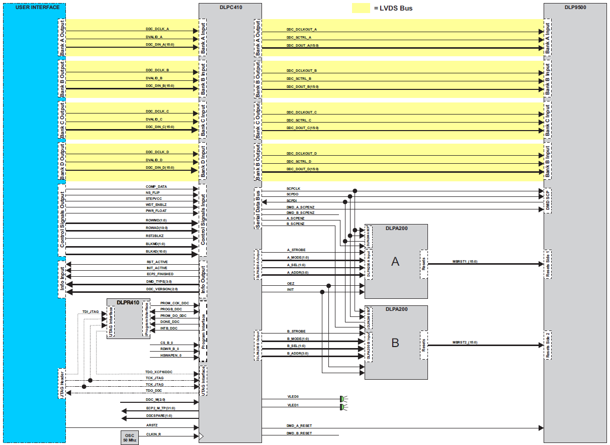
| BLOCK | NAME | BUS | TYPE | DLPC I/O | DESCRIPTION |
|---|---|---|---|---|---|
| A | DDC_DIN_A | 16 | LVDS | I | Data A bus Input |
| DVALID_A | LVDS | I | Bank A Valid Input Signal | ||
| DDC_DCLK_A | LVDS | I | Bank A Input Clock | ||
| B | DDC_DIN_B | 16 | LVDS | I | Data B bus Input |
| DVALID_B | LVDS | I | Bank B Valid Input Signal | ||
| DDC_DCLK_B | LVDS | I | Bank B Input Clock | ||
| C | DDC_DIN_C | 16 | LVDS | I | Data C bus Input |
| DVALID_C | LVDS | I | Bank C Valid Input Signal | ||
| DDC_DCLK_C | LVDS | I | Bank C Input Clock | ||
| D | DDC_DIN_D | 16 | LVDS | I | Data D bus Input |
| DVALID_D | LVDS | I | Bank D Valid Input Signal | ||
| DDC_DCLK_D | LVDS | I | Bank D Input Clock | ||
| Ctrl_Sig_In | COMP_DATA | SE | I | Compliment Data (0 <--> 1) | |
| NS_FLIP | SE | I | Top/Bottom image flip on DMD | ||
| STEPVCC | SE | I | Not Used | ||
| WDT_ENBLZ | SE | I | DMD Mirror Clocking PulseWatchdog Timer Enable | ||
| PWR_FLOAT | SE | I | DMD Power Good indicator | ||
| ROWMD | 2 | SE | I | DMD Row Mode | |
| ROWAD | 11 | SE | I | DMD Row Address | |
| RST2BLK | SE | I | Dual Block Reset bit | ||
| BLKMD | 2 | SE | I | Block Mode | |
| BLKAD | 11 | SE | I | Block Address | |
| Info Out | RST_ACTIVE | SE | O | DMD Reset in Progress | |
| INIT_ACTIVE | SE | O | DLPC410 Initilization Routine Active | ||
| ECP2_FINISHED | SE | O | DLPR410 Initialization Routine Complete | ||
| DMD_TYPE | 4 | SE | O | DMD Attached Type | |
| DDC_VERSION | 3 | SE | O | DLPC410 Firmware Rev Number | |
| RESET | ARST | SE | I | DLPC410 Reset | |
| CLOCK | CLKIN_R | SE | I | Reference Clock |
Device Functional Modes
The DLP9500 has only one functional mode; it is set to be highly optimized for low latency and high speed in
generating mirror clocking pulses and timings.
When operated with the DLPC410 controller in conjunction with the DLPA200 drivers, the DLP9500 can be
operated in several display modes. The DLP9500 is loaded as 15 blocks of 72 rows each. The first 64 bits of
pixel data and last 64 bits of pixel data for all rows are not visible. Below is a representation of how the image is
loaded by the different micromirror clocking pulse modes. Figure 13, Figure 14, Figure 15, and Figure 16 show
how the image is loaded by the different micromirror clocking pulse modes.
There are four micromirror clocking pulse modes that determine which blocks are reset when a micromirror
clocking pulse command is issued:
• Single block mode
• Dual block mode
• Quad block mode
• Global mode
Single Block Mode
In single block mode, a single block can be loaded and reset in any order. After a block is loaded, it can be reset
to transfer the information to the mechanical state of the mirrors.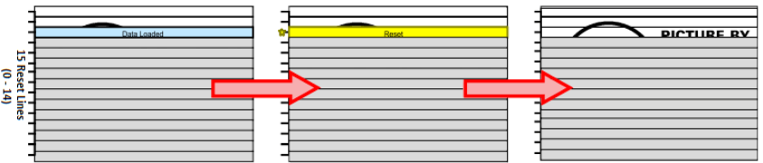
Dual Block Mode
In dual block mode, reset blocks are paired together as follows (0-1), (2-3), (4-5), (6-7), (8-9), (10-11), (12-13),
and (14). These pairs can be reset in any order. After data is loaded a pair can be reset to transfer the
information to the mechanical state of the mirrors.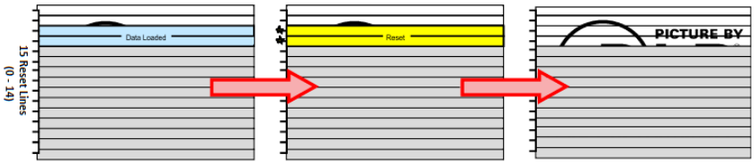
Quad Block Mode
In quad block mode, reset blocks are grouped together in fours as follows (0-3), (4-7), (8-11) and (12-14). Each
quad group can be randomly addressed and reset. After a quad group is loaded, it can be reset to transfer the
information to the mechanical state of the mirrors.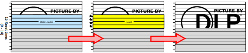
Global Block Mode
In global mode, all reset blocks are grouped into a single group and reset together. The entire DMD must be
loaded with the desired data before issuing a Global Reset to transfer the information to the mechanical state of
the mirrors.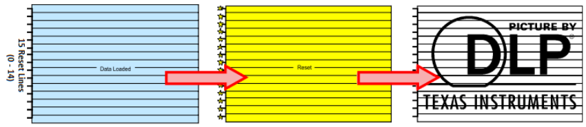
DLPC410 DLP Digital Controller [dlps024c.pdf]
Updated by Frédéric Blanc almost 8 years ago · 13 revisions